
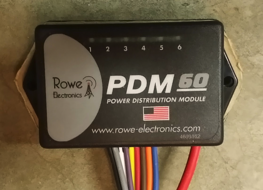
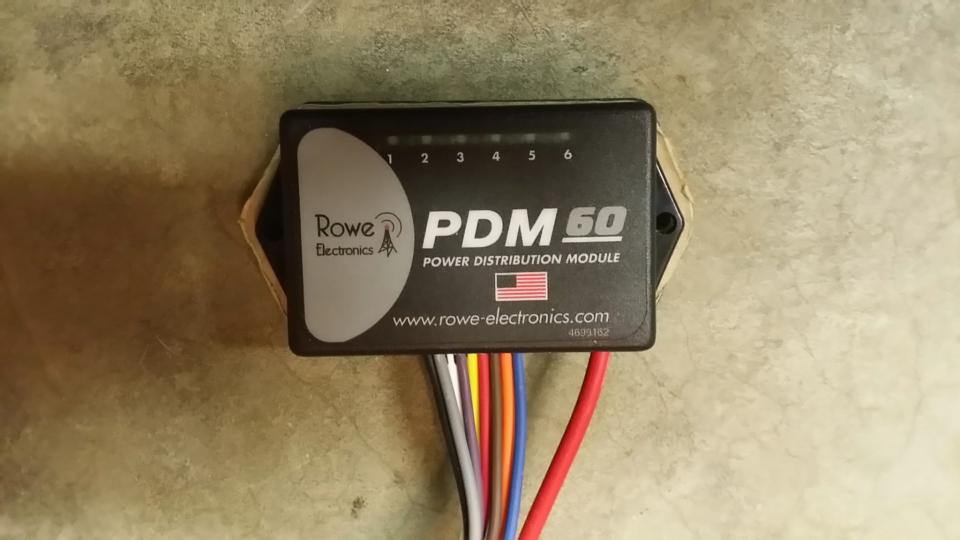
I had blown one of my auxiliary driving lights because I had gotten in the habit of just leaving them on all the time. As soon as I turned the ignition on they turned on, and in turn were subjected to the power fluctuations of engine start since they were wired to an ignition switched source. I needed a solution to prevent this from happening - enter the PDM 60.
The PDM 60 gave me the ability to not only eliminate fuses and relays, but create on and off delays for the outputs. Take a look at Rowe Electronic’s PDM 60 programming manual and Quick Start Guide and you can see that there is a lot of flexibility in the delays and circuit trigger options. My only complaint is that the “Delay On” timer, if used, applies to all circuits regardless of the mode selected, and the “Delay Off” timer applies to all circuits selected for delay off - you cannot have a different delay on or off per circuit, so you have to compromise a bit - at least in my case I did. There are other products out there that provide a similar solution, but the PDM 60 seemed to be the least over-done - I like to keep things simple, silly, stupid as much as possible.
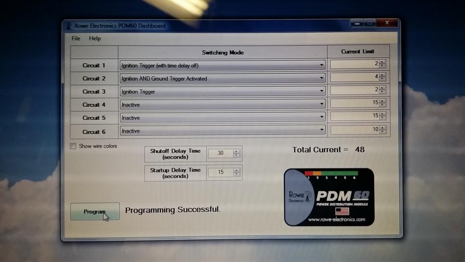
In this application I was going to use three of the six available outputs. This may give you some ideas on how you want your own setup to function, and get the creative thoughts flowing.
Output 1 - Garmin Montana GPS
- Ignition trigger. 15 second startup delay and 30 seconds shutoff delay limited at 2 amps
- Output stays on for 30 seconds after ignition off (not engine kill). Garmin products automatically shutoff 30 seconds after external power is lost unless you tell them not to at which point they switch to the internal battery. This gives me time to poke at the GPS after I turn off the bike, or just let it shut off automatically after 60 seconds.
Output 2 - Driving Lights
- Ignition & Ground trigger. 15 second startup delay limited at 4 amps
- I am using a handlebar mounted switch to provide the ground trigger. This way I can still turn the lights on and off when the ignition is on. If I leave the switch on indefinitely, the lights simply turn on 15 seconds after I turn on the ignition and turn off when I turn off the ignition. A review of that switch can be found here
- Output shuts off immediately when ignition is shut off regardless of handlebar switch position. If I use the kill switch rather than the ignition to shut down the bike the lights stay on if the switch is on.
Output 3 - Coil of slave ABS Disable Relay - See detailed article on this topic here
- Ignition Trigger. 15 second startup delay limited at 2 amps.
- I am using a handlebar mounted switch to provide a ground to one side of an ABS disable relay’s coil. The PDM 60 provides the 12VDC to the other side of the coil. Yes, I could have used the PDM 60 to control the ABS disable without a relay, but as I needed to switch a 30 Amp circuit I chose to use a slave relay. A review of the handlebar mounted switch can be found here
- Output shuts off immediately when ignition is shut off. If I use the kill switch rather than the ignition to shut down, the ABS disconnect relay remains active. If I leave the ABS disable switch on indefinitely the ABS automatically disables 15 seconds after ignition on.
I went with a 15 second startup delay to allow the ECU to complete it’s startup, and for bike startup. 15 seconds after the ignition is switched on all outputs turn on except those selected for ignition & ground trigger, and those selected as inactive.
WARNING: There is a blurb in the manual that I almost missed. DO NOT attempt to program your PDM 60 while its 12VDC input is connected. According to the manual this can damage the unit. I had mine completely wired up, went to program, and was glad I read ahead or I may have killed the PDM 60.
WARNING: Pay special attention to how you plug in the programming cable. It will plug in in two different directions. One direction programs the PDM 60, the other direction destroys the PDM 60. There is a warning to this effect in the manual as well, but take your time making sure you orient the programming lead correctly.
NOTE: As per the programming manual you will need Microsoft’s .NET framework version 4 installed on the programming laptop/pc. The programmer installation file installs the USB drivers you’ll need for the programming cable. Once installed the programmer is very easy to use.

Yamaha Super Tenere Specific:
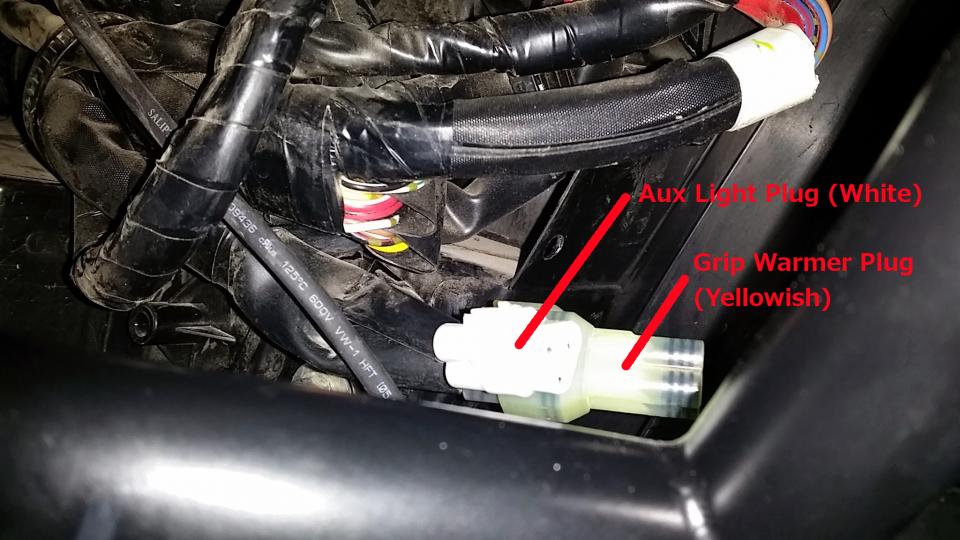
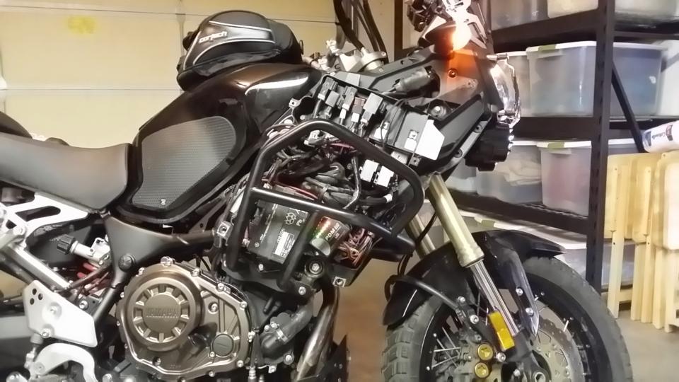
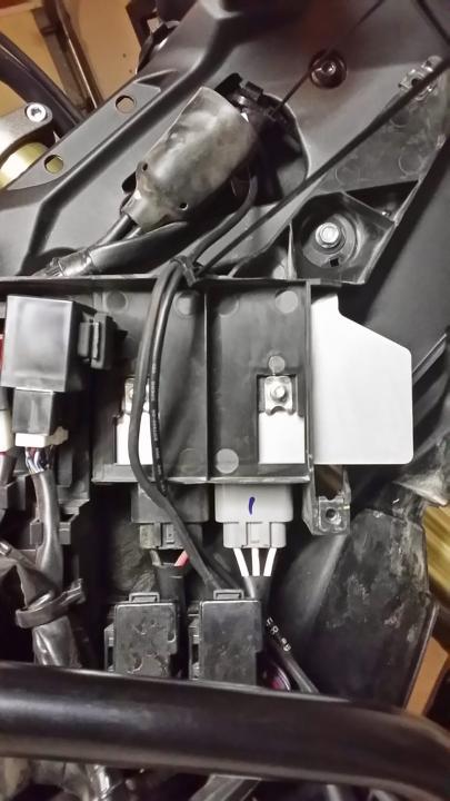
On the Yamaha Super Tenere the easiest and cleanest place to get your ground reference and ignition trigger is the stock aux lighting wire harness which is likely unused on your bike. This wiring harness is located under the lower right cover near the stock toolkit location. Connectors and rubber seals for this plug can be sourced from your friendly Yamaha dealer and cost less than a dollar if not free. There are two plugs/harnesses stashed just to the left of the stock toolkit location. One is triangular and has three connections that don’t go anywhere, and one is square and has four connections that don’t go anywhere. Take the male side of the, white, three connection plug down to your Yamaha dealer and ask for the connectors and rubber seals needed to complete the male side of this plug. (The four connector plug is for Yamaha accessory grip heaters). You can find a detailed writeup on how to utilize this plug within my ABS Disable Switch Article about half way down
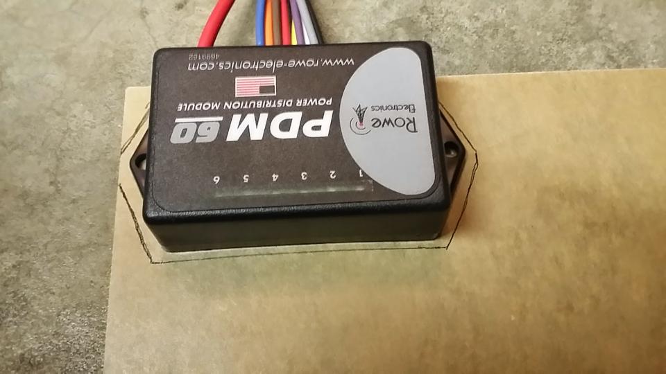
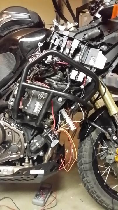
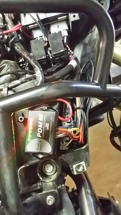
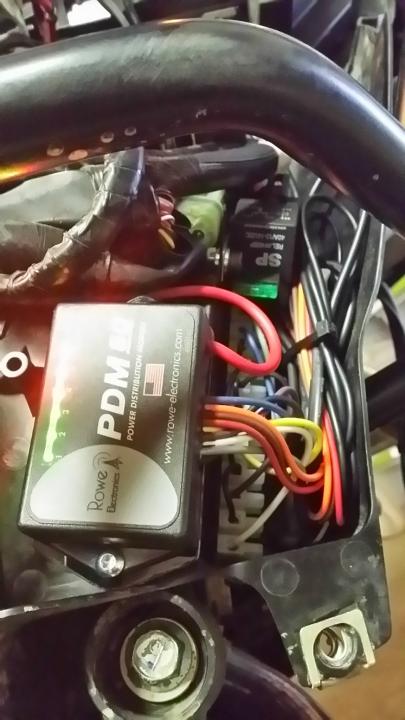
I mounted my PDM 60 in the lower part of the electronics bay just behind the stock toolkit location. All my wiring and terminal strip is located in the stock toolkit’s location. I got rid of that useless piece of kit long ago, and created my own toolkit which I keep in my panniers. I made a mounting plate for the PDM 60 out of some 1/4” acrylic sheet (), bolted the PDM to the mounting plate, and used velcro to affix the PDM and mounting plate to the flat spot in the electronics bay. I used a 12 point terminal strip for all my connections to keep everything nice and tidy.
For wire routing to the driving lights and GPS I went up under the upper right side cover, through an existing wiring chase, and to the lights/GPS wrapping everything in heat shrink tubing. Pictures speak 1,000 words - see pictures below for reference.

Want to know what others think about this product or want to share your experience? Checkout our Reviews.


Recommended Comments
Join the conversation
You can post now and register later. If you have an account, sign in now to post with your account.