Search the Community
Showing results for tags 'Yamaha'.
-
0 reviews
GENERAL INFORMATION Model: Yamaha XTZ660 Tenere Year: 2008 Category: Enduro / offroad Rating: 71.3 out of 100. ENGINE AND TRANSMISSION Displacement: 660.00 ccm (40.27 cubic inches) Engine type: Single cylinder, four-stroke Power: 47.74 HP (34.8 kW)) Torque: 57.50 Nm (5.9 kgf-m or 42.4 ft.lbs) @ 5870 RPM Compression: 10.0:1 Bore x stroke: 100.0 x 84.0 mm (3.9 x 3.3 inches) Fuel system: Injection Fuel control: SOHC Ignition: TCI Lubrication system: Dry sump Cooling system: Liquid Gearbox: 5-speed Transmission type, final drive: Chain Clutch: Wet, multiple-disc coil spring CHASSIS, SUSPENSION, BRAKES AND WHEELS Frame type: Steel tube diamond shaped Front suspension: Telescopic forks Front suspension travel: 120 mm (4.7 inches) Rear suspension: Swingarm (monocross) Rear suspension travel: 117 mm (4.6 inches) Front tyre: 90/90-M21 Rear tyre: 130/80-M17 Front brakes: Double disc Front brakes diameter: 298 mm (11.7 inches) Rear brakes: Single disc Rear brakes diameter: 245 mm (9.6 inches) PHYSICAL MEASURES AND CAPACITIES Dry weight: 183.0 kg (403.4 pounds) Power/weight ratio: 0.2609 HP/kg Seat height: 895 mm (35.2 inches) If adjustable, lowest setting. Overall height: 1,477 mm (58.1 inches) Overall length: 2,246 mm (88.4 inches) Overall width: 865 mm (34.1 inches) Ground clearance: 245 mm (9.6 inches) Wheelbase: 1,505 mm (59.3 inches) Fuel capacity: 22.00 litres (5.81 gallons) OTHER SPECIFICATIONS Starter: Electric -

0 reviews
GENERAL INFORMATION Model: Yamaha Super Tenere ES Year: 2014 Category: Super motard ENGINE AND TRANSMISSION Displacement: 1199.00 ccm (73.16 cubic inches) Engine type: Twin, four-stroke Compression: 11.0:1 Bore x stroke: 98.0 x 79.5 mm (3.9 x 3.1 inches) Fuel system: Injection. Fuel Injection with YCC-T Fuel control: DOHC Ignition: TCI: Transistor Controlled Ignition Cooling system: Liquid Gearbox: 6-speed Transmission type, final drive: Shaft drive (cardan) Driveline: Constant mesh Fuel consumption: 5.47 litres/100 km (18.3 km/l or 43.00 mpg) Greenhouse gases: 126.9 CO2 g/km. (CO2 - Carbon dioxide emission) CHASSIS, SUSPENSION, BRAKES AND WHEELS Rake (fork angle): 28.0° Front suspension: Telescopic fork, 43mm tube, adjustable preload, compression and rebound damping, 7.5-in travel Front suspension travel: 191 mm (7.5 inches) Rear suspension: Monoshock, adjustable preload and rebound damping, 7.5-in of travel Rear suspension travel: 191 mm (7.5 inches) Front tyre: 110/80-R19 Rear tyre: 150/70-R17 Front brakes: Double disc. ABS. Hydraulic. Front brakes diameter: 310 mm (12.2 inches) Rear brakes: Single disc Rear brakes diameter: 282 mm (11.1 inches) PHYSICAL MEASURES AND CAPACITIES Weight incl. oil, gas, etc: 262.2 kg (578.0 pounds) Seat height: 846 mm (33.3 inches) If adjustable, lowest setting. Overall height: 1,410 mm (55.5 inches) Overall length: 2,256 mm (88.8 inches) Overall width: 980 mm (38.6 inches) Wheelbase: 1,539 mm (60.6 inches) Fuel capacity: 23.09 litres (6.10 gallons) OTHER SPECIFICATIONS Starter: Electric Factory warranty: 1 Year Limited Factory Warranty -
0 reviews
GENERAL INFORMATION Model: Yamaha Super Tenere ES Year: 2015 Category: Super motard ENGINE AND TRANSMISSION Displacement: 1199.00 ccm (73.16 cubic inches) Engine type: Twin, four-stroke Compression: 11.0:1 Bore x stroke: 98.0 x 79.5 mm (3.9 x 3.1 inches) Fuel system: Injection. Fuel Injection with YCC-T Fuel control: DOHC Ignition: TCI: Transistor Controlled Ignition Cooling system: Liquid Gearbox: 6-speed Transmission type, final drive: Shaft drive (cardan) Driveline: Constant mesh Fuel consumption: 5.47 litres/100 km (18.3 km/l or 43.00 mpg) Greenhouse gases: 126.9 CO2 g/km. (CO2 - Carbon dioxide emission) CHASSIS, SUSPENSION, BRAKES AND WHEELS Rake (fork angle): 28.0° Front suspension: Telescopic fork, 43mm tube, adjustable preload, compression and rebound damping, 7.5-in travel Front suspension travel: 191 mm (7.5 inches) Rear suspension: Monoshock, adjustable preload and rebound damping, 7.5-in of travel Rear suspension travel: 191 mm (7.5 inches) Front tyre: 110/80-R19 Rear tyre: 150/70-R17 Front brakes: Double disc. ABS. Hydraulic. Front brakes diameter: 310 mm (12.2 inches) Rear brakes: Single disc Rear brakes diameter: 282 mm (11.1 inches) PHYSICAL MEASURES AND CAPACITIES Weight incl. oil, gas, etc: 262.2 kg (578.0 pounds) Seat height: 846 mm (33.3 inches) If adjustable, lowest setting. Overall height: 1,410 mm (55.5 inches) Overall length: 2,256 mm (88.8 inches) Overall width: 980 mm (38.6 inches) Wheelbase: 1,539 mm (60.6 inches) Fuel capacity: 23.09 litres (6.10 gallons) OTHER SPECIFICATIONS Starter: Electric Factory warranty: 1 Year Limited Factory Warranty Color options: Candy Red, Matte Silver -
0 reviews
GENERAL INFORMATION Model: Yamaha Super Tenere Year: 2014 Category: Super motard ENGINE AND TRANSMISSION Displacement: 1199.00 ccm (73.16 cubic inches) Engine type: Twin, four-stroke Compression: 11.0:1 Bore x stroke: 98.0 x 79.5 mm (3.9 x 3.1 inches) Fuel system: Injection. Fuel Injection with YCC-T Fuel control: DOHC Ignition: TCI: Transistor Controlled Ignition Cooling system: Liquid Gearbox: 6-speed Transmission type, final drive: Shaft drive (cardan) Driveline: Constant mesh Fuel consumption: 5.47 litres/100 km (18.3 km/l or 43.00 mpg) Greenhouse gases: 126.9 CO2 g/km. (CO2 - Carbon dioxide emission) CHASSIS, SUSPENSION, BRAKES AND WHEELS Rake (fork angle): 28.0° Front suspension: Telescopic fork, 43mm tube, adjustable preload, compression and rebound damping, 7.5-in travel Front suspension travel: 191 mm (7.5 inches) Rear suspension: Monoshock, adjustable preload and rebound damping, 7.5-in of travel Rear suspension travel: 191 mm (7.5 inches) Front tyre: 110/80-R19 Rear tyre: 150/70-R17 Front brakes: Double disc. ABS. Hydraulic. Front brakes diameter: 310 mm (12.2 inches) Rear brakes: Single disc Rear brakes diameter: 282 mm (11.1 inches) PHYSICAL MEASURES AND CAPACITIES Weight incl. oil, gas, etc: 262.2 kg (578.0 pounds) Seat height: 846 mm (33.3 inches) If adjustable, lowest setting. Overall height: 1,410 mm (55.5 inches) Overall length: 2,256 mm (88.8 inches) Overall width: 980 mm (38.6 inches) Wheelbase: 1,539 mm (60.6 inches) Fuel capacity: 23.09 litres (6.10 gallons) OTHER SPECIFICATIONS Starter: Electric Factory warranty: 1 Year Limited Factory Warranty -
 WASHINGTON, D.C. - April 9, 2015 - (Motor Sports Newswire) - RECALL Subject: Shift Cam Segment Stopper may Fracture Report Receipt Date: MAR 25, 2015 NHTSA Campaign Number: 15V176000 Component(s): POWER TRAIN Potential Number of Units Affected: 4,900 Products Associated with this Recall 2015 Super Tenere and Tenere ES SUMMARY: Yamaha Motor Corporation, USA (Yamaha) is recalling certain model year 2015 FJ-09 (FJ09F/FC), FZ-09 (FZ09F/FC), FZ6R (FZ6RF/FC), Super Tenere (XTZ12F/FC), Super Tenere ES (XTZ12EF/EFC), and R6 (YZF-R6) motorcycles manufactured September 1, 2014, to November 17, 2014. The affected motorcycles may have an incorrectly manufactured shift cam segment stopper, having a sharp edge on the inside of the bend instead of a smooth radius. As a result, the stopper can crack and possibly fracture at this sharp edge. CONSEQUENCE: If the stopper fractures, the transmission may not shift properly, increasing the risk of a crash. REMEDY: Yamaha will notify owners, and dealers will replace the shift shaft assembly with a new one, free of charge. The recall is expected to begin in April 2015. Owners may contact Yamaha customer service at 1-800-962-7926. NOTES: Owners may also contact the National Highway Traffic Safety Administration Vehicle Safety Hotline at 1-888-327-4236 (TTY 1-800-424-9153), or go to www.safercar.gov.
 -
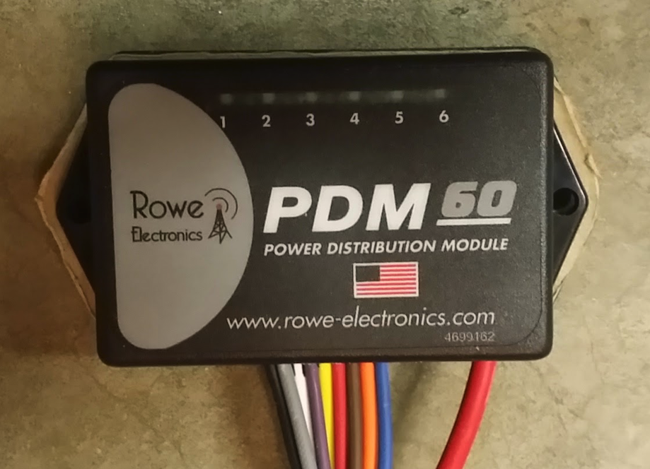 I had blown one of my auxiliary driving lights because I had gotten in the habit of just leaving them on all the time. As soon as I turned the ignition on they turned on, and in turn were subjected to the power fluctuations of engine start since they were wired to an ignition switched source. I needed a solution to prevent this from happening - enter the PDM 60. The PDM 60 gave me the ability to not only eliminate fuses and relays, but create on and off delays for the outputs. Take a look at Rowe Electronic’s PDM 60 programming manual and Quick Start Guide and you can see that there is a lot of flexibility in the delays and circuit trigger options. My only complaint is that the “Delay On” timer, if used, applies to all circuits regardless of the mode selected, and the “Delay Off” timer applies to all circuits selected for delay off - you cannot have a different delay on or off per circuit, so you have to compromise a bit - at least in my case I did. There are other products out there that provide a similar solution, but the PDM 60 seemed to be the least over-done - I like to keep things simple, silly, stupid as much as possible. In this application I was going to use three of the six available outputs. This may give you some ideas on how you want your own setup to function, and get the creative thoughts flowing. Output 1 - Garmin Montana GPS Ignition trigger. 15 second startup delay and 30 seconds shutoff delay limited at 2 amps Output stays on for 30 seconds after ignition off (not engine kill). Garmin products automatically shutoff 30 seconds after external power is lost unless you tell them not to at which point they switch to the internal battery. This gives me time to poke at the GPS after I turn off the bike, or just let it shut off automatically after 60 seconds. Output 2 - Driving Lights Ignition & Ground trigger. 15 second startup delay limited at 4 amps I am using a handlebar mounted switch to provide the ground trigger. This way I can still turn the lights on and off when the ignition is on. If I leave the switch on indefinitely, the lights simply turn on 15 seconds after I turn on the ignition and turn off when I turn off the ignition. A review of that switch can be found here Output shuts off immediately when ignition is shut off regardless of handlebar switch position. If I use the kill switch rather than the ignition to shut down the bike the lights stay on if the switch is on. Output 3 - Coil of slave ABS Disable Relay - See detailed article on this topic here Ignition Trigger. 15 second startup delay limited at 2 amps. I am using a handlebar mounted switch to provide a ground to one side of an ABS disable relay’s coil. The PDM 60 provides the 12VDC to the other side of the coil. Yes, I could have used the PDM 60 to control the ABS disable without a relay, but as I needed to switch a 30 Amp circuit I chose to use a slave relay. A review of the handlebar mounted switch can be found here Output shuts off immediately when ignition is shut off. If I use the kill switch rather than the ignition to shut down, the ABS disconnect relay remains active. If I leave the ABS disable switch on indefinitely the ABS automatically disables 15 seconds after ignition on. I went with a 15 second startup delay to allow the ECU to complete it’s startup, and for bike startup. 15 seconds after the ignition is switched on all outputs turn on except those selected for ignition & ground trigger, and those selected as inactive. WARNING: There is a blurb in the manual that I almost missed. DO NOT attempt to program your PDM 60 while its 12VDC input is connected. According to the manual this can damage the unit. I had mine completely wired up, went to program, and was glad I read ahead or I may have killed the PDM 60. WARNING: Pay special attention to how you plug in the programming cable. It will plug in in two different directions. One direction programs the PDM 60, the other direction destroys the PDM 60. There is a warning to this effect in the manual as well, but take your time making sure you orient the programming lead correctly. NOTE: As per the programming manual you will need Microsoft’s .NET framework version 4 installed on the programming laptop/pc. The programmer installation file installs the USB drivers you’ll need for the programming cable. Once installed the programmer is very easy to use. Yamaha Super Tenere Specific: On the Yamaha Super Tenere the easiest and cleanest place to get your ground reference and ignition trigger is the stock aux lighting wire harness which is likely unused on your bike. This wiring harness is located under the lower right cover near the stock toolkit location. Connectors and rubber seals for this plug can be sourced from your friendly Yamaha dealer and cost less than a dollar if not free. There are two plugs/harnesses stashed just to the left of the stock toolkit location. One is triangular and has three connections that don’t go anywhere, and one is square and has four connections that don’t go anywhere. Take the male side of the, white, three connection plug down to your Yamaha dealer and ask for the connectors and rubber seals needed to complete the male side of this plug. (The four connector plug is for Yamaha accessory grip heaters). You can find a detailed writeup on how to utilize this plug within my ABS Disable Switch Article about half way down I mounted my PDM 60 in the lower part of the electronics bay just behind the stock toolkit location. All my wiring and terminal strip is located in the stock toolkit’s location. I got rid of that useless piece of kit long ago, and created my own toolkit which I keep in my panniers. I made a mounting plate for the PDM 60 out of some 1/4” acrylic sheet (), bolted the PDM to the mounting plate, and used velcro to affix the PDM and mounting plate to the flat spot in the electronics bay. I used a 12 point terminal strip for all my connections to keep everything nice and tidy. For wire routing to the driving lights and GPS I went up under the upper right side cover, through an existing wiring chase, and to the lights/GPS wrapping everything in heat shrink tubing. Pictures speak 1,000 words - see pictures below for reference. Want to know what others think about this product or want to share your experience? Checkout our Reviews.
 -
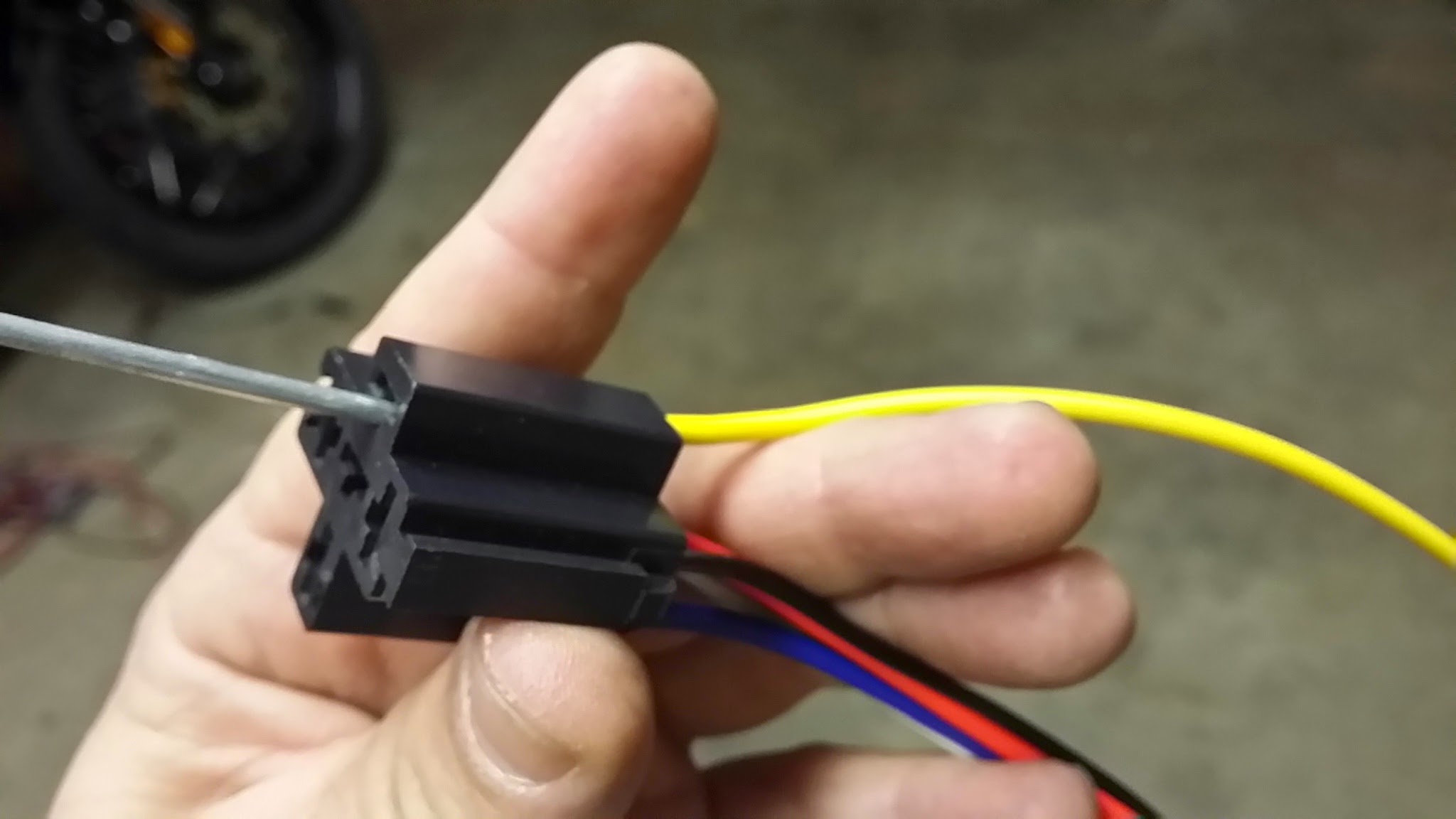 Disclaimer: You disable your ABS at your own risk. Damage to yourself, or your bike, resulting from this modification either during the modification process itself, or while riding with ABS disabled is solely your responsibility. Ok, now that that BS is behind us lets get to the modification. Lets get right down to it! It's really simple actually - the basic premise is that you want to be able to defeat the ABS when riding off-road or on loose surfaces to decrease your stopping distance, allow you to lock up the rear, etc., but we are not going to get into off-road riding techniques in this article. The simplest way to defeat the ABS is to simply pull the ABS Motor fuse, but that's a pain. You have to take off a body panel, remove the fuse, re-install the body panel, and then not lose the fuse. There is a safe way to accomplish this electronically however, without risk of damage to the bike's electronics. Here's what you'll need: A fused single pole double throw (SPDT) relay such as the one found here: http://www.autotoys.com/x/product.php?productid=18599#tabs . You don't have to use a fused relay as we are installing all our circuitry after the factory ABS motor fuse, but I’m anal and like to fuse my relay contacts. A relay socket for your relay like the one found here: http://www.autotoys.com/x/product.php?productid=320 which we will modify slightly. An on off switch of your choice. This can be handlebar mounted, chassis mounted, whatever. The main thing is it simply needs to be an on/off switch (not momentary) Three .250 12 AWG Female quick disconnects like those found here: http://www.autozone.com/ignition/electrical-wire-connector/dorman-quick-disconnect-terminal/296848_0_0/ One .250 12 AWG Male quick disconnect like the one found here: http://www.autozone.com/ignition/electrical-wire-connector/dorman-quick-disconnect-terminal/296897_0_0/ Some heat shrink tubing big enough to fit over the .250 connectors About four feet of 12 gauge stranded wire. Three pieces of 16 gauge stranded wire in 1 foot lengths in 3 colors (Red/Black/Yellow) One short bolt, locknut, and washers to mount the relay Connectors and rubber seals for the super-top-secret, unused, stock, auxiliary light plug located under the lower right cover near the stock toolkit location. These can be sourced from your friendly Yamaha dealer and cost less than a dollar if not free. There are two plugs stashed just to the left of the stock toolkit location. One is triangular and has three connections that don’t go anywhere, and one is square and has four connections that don’t go anywhere. Take the male side of the, white, three connection plug down to your Yamaha dealer and ask for the connectors and rubber seals needed to complete the male side of this plug. (The four connector plug is for Yamaha accessory grip heaters). Once you have your shopping list fulfilled let’s get all our materials ready. First we need to remove the insulation off the three .250 12 AWG female quick disconnects. Simply use a pair of needle nose pliers to twist, loosen, and pry the insulation off the stem. We don’t want any insulation on these connectors Cut two 3” pieces of heat shrink tubing large enough to fit over the 12 AWG Male quick disconnect Remove the wires and connectors 87, 87a, and 30 from your relay socket. Do this by inserting a small screwdriver into the hole near the connector (from the plug side), pushing in on the screwdriver while pulling the wire out from the rear Cut two pieces of your 12 gauge wire to about two feet each. Strip both ends of each wire back about 1/4 inch. Crimp or solder two of the .250 12 AWG female quick disconnects onto each end of one wire. Crimp or solder one of the .250 12 AWG female quick disconnects, and the one .250 12 AWG male quick disconnect onto the other two foot length of wire. NOTE: When attaching the wire onto the connectors make sure the end of the wire does not protrude past the sleeve of the connector as this will interfere with the locking mechanism inside the sockets later. Slide both 3” pieces of heat shrink over the wire with the male/female disconnects. Snap the female end of your female/male wire into the relay socket #87a (Normally Closed) from the rear. Snap one of the female ends of your female/female wire into the relay socket #30 (Common) from the rear. You will not be using terminal #87 (Normally Open) - leave this removed wire out of the socket. If this wire from terminal #87 is left in place 12VDC will be present on this lead when your ABS is disabled. Install the relay onto the relay socket. Sometimes the new female disconnects won’t snap into the socket properly. Don't worry too much about this - just hold the wires into the socket as your push the relay into the socket and ensure a full connection on all leads of the relay to socket. Strip both ends of your 1 foot lengths of 16 gauge wire back about 1/4 inch. Crimp or solder the small spades you got from your friendly Yamaha dealer onto one end of each of these wires. Insert them fully into the sockets in the plug from the rear paying special attention to match the colors with the colors in the female end of the socket on the bike (Yellow to stripe). You can grasp the connector ends inside the plug with a small needle nose pliers to help pull the spade connectors into the socket. We won’t be using the red wire, but make it anyway for future use and cap off the end. Slide the rubber seals over the wires and down into the holes in the plug after you have inserted the spades into the plug fully. It would also be a good idea to heat shrink the three wires together and make your own harness to clean it all up. Now you are done with prep - remove the lower right, plastic body cover from the motorcycle to expose the battery and motorcycle's wiring. (the picture shows the upper cover removed as well - this is not necessary) Disconnect your battery! You may think you can do the rest of this without doing so, but all it takes is one slip of a screwdriver, or one dropped wire in just the right place and you have blown fuses or worse. Save yourself the headache and Murphy’s law and just disconnect the battery. If you haven’t already done so, remove the factory Yamaha toolkit, throw it over your shoulder, and create your own to store in your luggage. The factory toolkit for just about any motorcycle is a bauble thrown in by the manufacturer to say it’s there, and is close to worthless. There are many articles on the topic of what you need in your own toolkit. We will be using the factory toolkit’s storage location for our relay location. if you insist on keeping the toolkit, there are other places under this cover you can place your relay - proceed as desired. Locate the white plastic connector between the two 30A fuses just above the battery, depress the release catch, and unplug the connector. The large, 12 gauge, red wire feeding into this connector is the 12VDC supply to the ABS motor. (see picture below) Using a pair of snips, carefully cut a slit back in the black insulation around this wiring harness a couple inches to give you room for future steps. Be very careful not to nick or cut the insulation of the wires in the harness. Examine the plug side of this connector. note the location of the connector for the 12 gauge wire. There is a plastic catch inside this plastic connector that locks the metal connector from being removed. If you insert a small, flat blade screwdriver into the plug side of the connector you want to release, and wiggle it around a bit you will release the catch and be able to remove the connector. There is really no way to take a picture of this, so you’ll have to experiment until you get the 12 gauge red wire and it’s connector removed. In the picture the white plug is still plugged in - yours won’t be. I was experimenting when I took this picture, so my plug was plugged in. Insert the female connector coming from #30 of your relay socket (Common) into the white plug that you just removed the connector from. Push the female connector into the socket until it snaps into place Insert the male connector coming from #87a of your relay socket (Normally Closed) into the female connector of the wire going to the ABS motor Slide one piece of heat shrink over this connection, heat to shrink, then slide the second piece of heat shrink over the first - heat to shrink. We want lots of protection here. Install your on/off switch of choice, and route the wires down to the area where you’ve chosen to house your relay. Plug your newly made 3 pin wiring harness into the factory auxiliary light harness. Again, make sure you plug this in correctly and match red to red, yellow to stripe, etc. If this plug is already used find another source of ignition switched 12VDC and ground for the next steps Connect one of the two leads coming from your on/off switch to #85 of your relay socket (Coil). Connect the other of the two leads coming from your on/off switch to the black wire (ground) coming from the factory auxiliary light harness you made. Connect the yellow wire from the factory auxiliary light harness (switched 12VDC) to #88 of your relay socket (Coil). If you chose to install your relay in the toolkit location, drill a small hole in the flange about midway up the rear portion of the toolkit’s cubby to mount the relay to. Run your Bolt, washers, and lock nut through the relay and hole to secure. Carefully stuff the wiring into the toolkit cavity and secure with your preferred method. You can use a zip tie or even use the factory rubber bungy that held the toolkit in. Re-stuff the factory hand grip and auxiliary light plugs into the cavity where you found them behind the factory toolkit location. That’s it - your done! Reconnect your battery and enjoy. The way this is wired you can safely leave your ABS switch in the closed position when you turn off and start the bike. there will be no parasitic draw from the relay's coil during power off as we used the switched 12VDC from the bike to the coil of the relay. As soon as you turn the bike on, and if your switch is closed, the ABS will disable. To re-enable the ABS you will have to open the switch, turn off the bike, and restart the bike. Enjoy!
 -
0 comments
Loving my Super Tenere!-
- 1
-

-
- SuperTenere
- Yamaha
- (and 1 more)
-
Someone is a happy guy today! PICKERINGTON, OH - January 22, 2015 - (Motor Sports Newswire) - When Bob J. Loguidice of Ramona, Calif., renewed his American Motorcyclist Association membership last February, it earned him the status of AMA Life Member and qualified him for the 2014 American Motorcyclist Association membership sweepstakes. Today, Loguidice won the sweepstakes prize, a 2014 Yamaha Super Ténéré motorcycle, courtesy of Yamaha Motor Corp. U.S.A. "I'm kind of stunned," said Loguidice when informed of the sweepstakes results. "But this is great news. This just shows what can happen when you have motorcycling interests as a high priority and keep up your AMA membership." AMA members who joined or renewed in 2014 got a chance to win the Super Ténéré. In addition, riders participating in the 2014 Yamaha Super Ténéré AMA National Adventure Riding Series earned additional entries in the sweepstakes. "We are very excited that Bob has won the Yamaha Super Ténéré," said Yamaha Motor Corp. USA Retail Sales Promotion Manager Martin Vivanco. "It's great to see the Ténéré going to an enthusiast with great passion for our sport. The Super Ténéré was built for the adventurous rider who wants to explore the open road and the path less taken, and Bob will have the opportunity to do both this year at a round of the AMA Super Ténéré Adventure Riding Series." Independent auditing and accounting firm Plante & Moran of Columbus, Ohio, administered the sweepstakes. Designed to ride for extended periods across just about any kind of navigable terrain in comfort and style, the Yamaha Super Ténéré serves as the perfect inspiration for the AMA National Adventure Riding Series. The bike, known as the ultimate transcontinental adventure machine, was improved for 2014 with a more powerful inline twin-cylinder engine, electronic cruise control, updated wind protection and heated grips as standard equipment. It also has sport and touring drive modes, traction control, anti-lock brakes, an adjustable seat and more. While Loguidice was elated to win the motorcycle, he was equally enthusiastic about protecting motorcyclists' rights through his AMA membership. "It's extremely important to maintain your membership," he said of the AMA and its commitment to protecting the motorcycle lifestyle. "You have to support the cause. If you don't protect your rights, you're going to lose them." AMA Life Member status comes with 25 consecutive years of membership dues. New and renewing AMA members already are earning an opportunity to win great prizes in the 2015 membership sweepstakes. Those joining or renewing their AMA memberships between Jan. 1, 2015, and Dec. 31, 2015, are automatically entered to win any of these 20 great prizes. Grand Prize -- A 2014 Suzuki Boulevard M109R or a 2015 Yamaha Super Ténéré -- two bikes and two chances to win. Annual Bonus Prize -- A Cardo Systems/Scala Rider G9 communications set that allows you to connect with as many as eight other riders; or a Shark Kage Ramp -- the ultimate in truck accessories for a motorcyclist. Quarterly Bonus Prize -- A TomTom Rider GPS unit, perfect for motorcyclists, will be given away to one winner on March 31, June 30, Sept. 30 and Dec. 31. Monthly Bonus Prize -- One BikeBandit.com gift card to be given away each month, January through December. Join the AMA by visiting www.americanmotorcyclist.com/membership/join. Those participating in the Yamaha Super Ténéré AMA National Adventure Riding Series are improving their odds as well. For the 2015 season calendar, see www.americanmotorcyclist.com/Riding/Dirt/EventsAndSeries/NationalAdventureRide/NationalAdventureRideSchedule.aspx. For more information about the Yamaha Super Ténéré, see www.yamahamotorsports.com.
-
 It all started in June of ’14. I found out I had a few days of vacation to use or lose at work, and at the last minute (3 days before departure) I decided to take a few days off and do a ride from Salt Lake City up through Yellowstone National park to Montana, and then back down through Idaho and back to Salt Lake. I called one of my riding buddies, he jumped on his Harley, and off we went. A motley pair - Me on my Tenere, and him on his Harley. There was no plan. It was ride, find a place to camp, ride, repeat. On day 1 we rode from Salt Lake up past Jackson Hole Wyoming with plans to camp in an ‘un-reserveable’ campground right outside the South entrance of Yellowstone. Well, as things sometimes go we found the un-reserveable campground not only full but half reserved. We rode around the loop of the campground once, and then started to ride the loop again just in case we’d missed something. As we rounded a corner on the second circuit of the campground this crazy German guy in a Touratech riding suit came bounding out of the bushes holding up his hand for us to stop. We did, and he began to inform us that the campground was full, but we we’re welcome to share his campspot with him and his wife! What luck! We quickly agreed, and thus a long-standing friendship was born with Claudia and Mirko of http://www.2ar.eu. 2 Adventure riders on the ride of their lives through the Americas on a charity Mission. We ended up spending the next few days with them as we explored Yellowstone, but I won’t get into that in this account. It was decided in those days that we would meet again in the Fall as they made their way back South from Canada to central America - we’d meet back up in Salt Lake City and do a tour of Southern Utah! Throughout the rest of the Summer I planned the Southern Utah Tour, figured out the routes we would take, and in early October Claudia and Mirko showed up with John Colyer of https://www.facebook.com/anomalyadv in tow. We spent a week in Salt Lake getting everybody ready, and then off we went - South for a planned 9 day tour of 6 National Parks - Zion, Bryce, Escalante, Capital Reef, Arches, And Canyonlands (Moab). It turned into 10 days however, as it got really windy on the day we we’re supposed to ride back to Salt Lake from Moab, and we all felt that was a good enough excuse to extend the trip another day! Hahaha. I won’t bore you with a long-winded account of the trip. That’s what video is for! Here’s a rather long, 15 minute account of the trip. Obviously you can’t fit 10 days of fun and adventure into a 15 minute video, but this was the best I could do! Enjoy! Oh, and if anyone wants to enjoy this route themselves HIT ME UP!!!! I’d be more than happy to do it again with a group, and I won’t even charge a tour-guide fee! Or, if you're interested, I can provide some links/coordinates of camping and trails along the route.
- 12 replies
-
- 3
-
-
- UnitedStates
- Adventure
- (and 8 more)
-
Here's a little edit of the first trail ride I took the Tenere on after installing my first set of Heidenau K60 Scouts. Tons of fun! This is climbing Bald Mountain in the Oquirr mountains just West of Salt Lake City Utah.